Sneaking Water Into the Building for a Chilled Water Rescue
This chilled water rescue involved a cooling system that was eating outside unit compressors and was no longer working. We got the call in May to get the cooling working by June for the summer season. Always up for a challenge, we said yes but then had to hustle to figure out what we were dealing with.
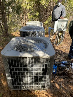
The existing system had three 5-ton outside units about 100 feet from the house. Buried line sets went from the condensers across the yard and then under the house where they popped up in a mechanical room in the center of the basement. The refrigerant from the outside units went to heat exchangers in the mechanical room that made chilled water which was then pumped to six air handlers installed throughout the building.
We figured that the compressors had failed from both a lack of oil return due to line set length and excessive short cycling. The outside units had been controlled by aquastats on the chilled water piping inside; if tighter control was wanted of the chilled water temperature, compressors would cycle on and off quite frequently. If a wider temperature swing of chilled water supply temps was permitted, the compressors would cycle on and off less frequently, but dehumidification capacity would be reduced. The end result was that compressors failed frequently and the system was unreliable. We figured that the cooling load was about 10 tons, but if two of the three outside units were down the five tons of capacity remaining would never meet the cooling load.
We knew that making the chilled water outside would eliminate the compressor failure issue and greatly increase system reliability. But that would mean getting chilled water supply and return pipes from the existing chiller pad to the mechanical room buried in the middle of the house. Could we successfully yank out the old line sets and reuse the buried conduit that was under the house? Would we be able to snake in chilled water supply and return pipes of suffcient size through the existing conduit? Once we yanked out the line sets, we would be committed to our chilled water concept...
Conduit Struggles and Ultimate Victory
Our next step was to determine what size chilled water supply and return lines would successfully connect 15 tons of cooling outside with the inside equipment. One constraint was that the remote chillers would be 100 feet away from the house. Another constraint was the diameter of the conduits that were buried under the building. Because of the sharp bends in the conduits that ran from the mechanical room in the middle of the basement all the way to the remote chiller pad, we had a real struggle removing the old line sets.
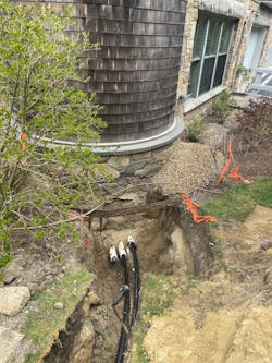
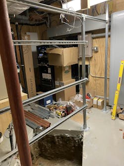
So we had the landscaper excavate from the remote chiller pad to the house and then cut the concrete floor in the mechanical room where the line sets came up. We cut off the conduits and line sets where they entered the building and removed the sharp elbows in the mechanical room floor where the conduits went from horizontal to vertical and rose up into the room. These steps let us finally pull out the old line sets that were under the building.
Next step was to snake in a black poly well pipe into the existing conduit—hoping that we could make it all the way to the center of the building where the mechanical room was. From the outside we pushed in a poly well line into one of the conduits at the edge of the building and were profoundly relieved when the poly well line appeared in the hole in the basement floor! Our chilled water rescue would be successful! It was all smooth sailing from here.
Outside Chiller Pad Work
Now that we had the chilled water supply and return pipes snaked under the building into the mechanical room, we could pivot to addressing the outside chiller installation. The landscaper was eager for us to finish so that they could re-sod the area before the summer season.
We put the supply and return lines into a trench the landscapers dug between the house and the chiller pad; the lines rose up out of the ground on the back side of the chiller pad. We pressure tested the lines and then the landscaper backfilled and re-sodded the trench—the homeowner never noticed the disruption to his lawn.
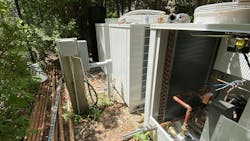
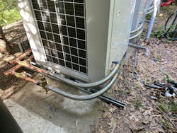
Our supply and return pipes were both 1-1/4” diameter—this informed our pressure drop calculations so we could design our outside and inside piping. We brought in three 5-ton Multiaqua units that were each equipped with internal pumps. The three chillers were connected to a 120-gallon buffer tank via supply and return mains. We used 2” copper for ease of assembly with press fittings. Because of time and budget constraints, we opted against a reverse return scheme and all three chillers got branch flow to the mains. As with all of our chiller projects, we connected the Multiaqua units via stainless steel flex hoses for ease of installation and alignment. Each of the chillers got an air separator for automatic air venting and purging as well as thermometers and ball valves. We used compression adapters to transition from the copper pipes to the black poly well lines at the edge of the chiller pit. We pressure tested and had no leaks—the press process was an amazing technology!
The three chillers were controlled by buffer tank temperature and staged on and off based on their chilled water setpoint.
Inside Pumps and Strut Framework
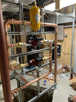
Now that the outside work was complete we could pivot to the inside mechanical room. We assembled a strut framework over the hole in the basement floor and carefully laid out all of our components to figure out our layout. We had measured the pressure drop across the existing chilled water circulator, so we knew the existing system pressure drop and flow from the pump curve. We sized our new circulators by adding the pressure drop from the 100-foot supply and return lines out to the remote chiller pad to the existing system pressure drop. There was no appetite from the homeowner for variable speed pumping as all six air handlers had three-way zone valves and the original system had been constant circulation. He didn’t want to expand the rescue project to include replacement of all of the zone valves; it was nearing the end of May and we had to get the cooling system back up and running.
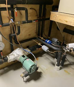
We put the air separator at the top of our strut framework and then worked our way down. We installed the two new circulators (with one pressure gauge each with ball valves on supply and return pressure taps so we could confirm flow), made our connections to the existing chilled water piping, and then dropped down into the hole in the basement floor. Using two more compression adaptors, we made the transition from copper to the poly well lines.
The two circulators were controlled by a Tekmar pump control that would do lead lag rotation of each pump.
System Insulation
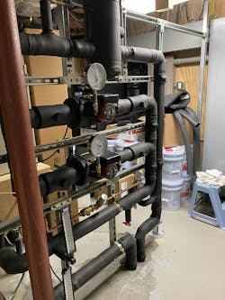
Hands down the worst part of any chilled water system is the insulating! All of the piping fun evaporates when one sits down to carefully wrap every fitting and pipe! Ideally, the installer of the piping is also the insulator so they can intelligently assemble the piping so that it is somewhat easy to insulate. If the two teams are separate, then there is usually a lot of cursing from the insulators because the fittings have been jammed together in a way that is hard to insulate. Circulator volutes are the absolute worst! It is indicative of our low energy prices that insulation clamshells are not commonly available for a lot of the circulators sold in the US.
I will make a bold statement here—I don’t see any place for fiberglass insulation in the chilled water world. People install it because “that’s the way we have always done it” and “the customer thinks that white pipes means he is getting the best.” We have ripped off so much fiberglass insulation used on chilled water piping that is absolutely saturated with condensation—the vapor barrier has failed and the yellow insulation wicks in water like crazy! Once it is soaked through, it has no more insulative value, and now the outside of the insulation is condensing moisture out of the air.
System Start Up and Commissioning - Don’t forget the glycol!
Once the inside and outside piping was insulated we fired up the three chillers and dropped the temp in the buffer tank. We started the inside circulators and tested operation and got great discharge air temperatures at all of the air handlers! We were excited to be done with this project—just in time for summer. We pumped in the glycol for antifreeze protection because we didn’t want to forget and then have to rescue one of our rescues—another chilled water rescue success!
About the Author
Brian Nelson
Brian Nelson is the co-owner of Nelson Mechanical Design, a “green” mechanical contractor serving the energy efficiency and home comfort needs of Martha's Vineyard, MA since 2004. The company designs, installs, and services just about anything to do with heating, cooling, domestic hot water, water treatment, geothermal, heat pumps, and radiant. NMD is committed to preserving the fabric of the Island it calls home. To learn more visit nmdgreen.com.
