Recipe for a Heating & Cooling System Rescue
My previous rescue stories have dealt with the HVAC and hydronic system rescue itself—the work we have done to a failed system to restore proper operation and improve efficiency and reliability.
It is worth taking a look at the part of our rescue process that happens before we start to make changes to the failed system. A rescue project doesn’t come with a solution or an install manual—we have to figure out what is going wrong and figure out how to make it work right. We get calls to do a rescue because the solution isn’t always obvious or straightforward; many times the installing contractor can’t figure out what is wrong or doesn’t know what to do to make thing work the way they should.
Because our trade is dedicated to achieving success (that is how we all get paid!) we sometimes get tunnel vision and have difficulty in zooming out to get a better vantage point when a system is not working well. That is when time should be spent on understanding “why” a system works, “how” it is designed to work effectively, and “what” is causing the issue.
I know in my career I learned a lot of things the hard way—struggling with an HVAC installation that just wasn’t working right—knowing that I wouldn’t get paid if I couldn’t get it right—and finally investing the time into studying system failures to improve our install process and avoid system issues in future installs. By definition, a rescue involves someone in the trades losing money over a system they can’t figure out. Ideally we can make some lemonade out of these lemons.
Performing and studying rescues is a great opportunity to learn, to improve, and to inspire (after all, the goal of learning about rescues is to never need one yourself). When people talk about difficulty in attracting young people into the trades, perhaps they haven’t seen the excitement that rescues create.
Currently we have three rescue projects in motion, and we have four of our techs under the age of 25 vying to be part of our rescue teams. Their bright minds are attracted to the challenge and the understanding that as our trade gets more and more complicated—seemingly every day—rescues will become more challenging and rewarding.
Recipe for a Successful Rescue
After doing enough rescue projects, we have developed the “recipe,” or important steps to take to achieve our goal of a functioning HVAC or hydronic system.
Firstly, we must understand what a correct install should look like and be able to identify where the failed installation deviates from the manufacturer’s guidelines.
Secondly, our diagnostic process must start with a sound understanding of the laws of physics that govern the operation of this failed system—this is the “why” of our investigation.
We must then look at what the “robot” (this is my term for the computer embedded on the equipment control boards) tells us through error codes, understand the limits of what the robot knows or is aware of, and do our independent testing to verify operation—we need to know “where” to start our investigation.
Thirdly, combine the above ingredients to come up with some approaches to resolving the issues facing the system—this is where our experience and skill set come into play. This is the “how” of our investigation.
Lastly, we must discuss pros and cons with the homeowner and arrive at a path forward—this is the critical time to explain the limits of our knowledge and the consequences of each rescue approach. This is the risk of doing rescue projects.
Step 1: What the System Should Look Like – Manufacturer’s Guidelines for a Correct Installation
One big reason we have so many rescues on Martha’s Vineyard is that just about every system installation is different. On the Vineyard we encounter every brand, every model, and every type of system designed to deliver heating, cooling, and ventilation. This means that there are a lot of brands we have to get familiar with.
In today’s world the manufacturers push towards pre-engineered solutions so that they can ensure the success of their installations while achieving rated capacity and efficiency.
They design and build equipment combinations and test them in a lab setting to figure out how they should be installed and then create instructions and guidelines to help the tech install them correctly.
Their goal is to eliminate guesswork, call backs, and warranty issues (and rescues).
We install a lot of mini split systems and note that they are highly pre-engineered with limited flexibility of which building blocks go together. The manufacturers provide selection software to assist the installer in making sure all of the parts of the puzzle (inside units and outside units) will go together correctly. We use our heat gain and loss analysis to help us select inside equipment. The selection software then chooses the correct branch box and outside unit that will deliver comfort and efficiency just like the manufacturer promised.
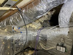
We also install a lot of inverter-driven heat pumps with ductwork based on either engineered drawings or our own designs using duct sizing software. The manufacturers know that distribution systems are a very common fault path that can lead to system trouble; if the ducts are correctly sized, the building blocks of outside unit and inside unit will deliver comfort and efficiency just like the manufacturer promised.
At the other end of the spectrum, we install a lot of boilers and chillers connected to radiant and hydronic heating and cooling systems. Here there is maximum flexibility in designing and choosing a distribution path to connect the equipment to the house’s heating and cooling load. This distribution path is also where the highest risk is for performance issues.
Step 2: Where Does the System Diverge from Manufacturer’s Guidelines – Mapping the Infrastructure
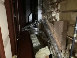
Once we have an understanding of the installation requirements presented by the manufacturer we can look for where the failed installation has deviated. This involves mapping the ductwork, piping, circulator sizes, line set lengths and sizes, control wiring lengths and wire type, flue pipe length and size and number of elbows, system water pressure, etc., etc., and ending with what area this system serves.
We need to determine if the heating and cooling load target changed (the original cooling setpoint was 74°F, now the kids want the cooling at 67°F), has the envelope changed (have lots of windows been added?), or has the intended use changed (system was not designed to meet the entire heating or cooling load). We can then compare what we have mapped out to what the manufacturer recommends. We commonly find pipes, ducts, and line sets that are too small that end up profoundly limiting system operation.
Sometimes a “rescue” situation is just a gross misunderstanding of what the system can do. We have had customers that complain bitterly about their cooling systems only to discover that they have kept the windows and open all day during the summer and then expect the correctly-sized cooling system to drop the room temperature from 80°F to 67°F in an hour!
The mapping process is critical as it will later provide valuable information on how to effect the rescue. Many times we aren’t able to just rip out the old system and install a new system. If we know information about the existing distribution infrastructure we can start to develop a plan to modify or re-use what we can.
Step 3: Diagnostic Process - What Do the Laws of Physics Tell Us?
Once we have an awareness of what the manufacturer wanted and what was actually installed, we can dive into our diagnostic process.
The rescue process is very similar to the service process. In our service department, we have morning “nuggets” before we discuss the service jobs of the day. These “nuggets” explain the “why” of previous or on-going service calls so that we can elevate the diagnostic skills of our service techs when they encounter interesting and unexpected operation. After “why” the next critical question is “where.” Knowing where to start the diagnostic process in an HVAC or hydronic system is critical to gaining understanding of what it is doing and how to correct it.
By zooming out our scope of investigation, we can expand from the focused service diagnostic to a system wide view that will permit seeing how all of the pieces work (or don’t) together. The first step is to understand the laws of physics and understand how they apply to our system.
I remind my rescue teams and myself that the system is doing exactly what it should be doing—just because we don’t understand it, the molecules and the laws of physics do.
Having the humility to observe and accept is the first step in seeing that the molecules are doing exactly what they should be doing.
It is profound to understand that in a rope tied between two poles, the rope molecules will all talk to each other to figure out which part of the rope is the lowest point. That all of the water molecules in a pool will seek the same level. That flowing water or refrigerant or electricity will always seek the easiest path. That heat will always flow from hot to cold. That high pressure will always flow to low pressure.
Just because you don’t understand what a system is doing it doesn’t mean that the physics of the situation are wrong.
Accepting that often permits a better awareness of what the system is actually doing and helps to clear out pre-conceptions of what the system “should” be doing. In fact, the realization that ALL molecules will ALWAYS follow the laws of physics is a great comfort—I would drop my tools and leave the trades if I couldn’t count on the laws of physics!
Step 4: Diagnostic Process - What is the Robot Telling Us (What Does It Really Know?)
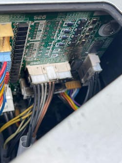
In our rescue process, we encounter error codes spit out by modern equipment. Each control board (I call it the “robot”) directs the operation of the equipment it is connected to and does its best to understand what is going on while the equipment is operating. If operation outside of normal parameters is detected, the robot generates an error code. These error codes can be very helpful in guiding our rescue effort or they can be quite misleading.
An awareness of “what” the robot actually “knows” is quite valuable in determining how much weight to put into any error code the robot spits out.
Young folks understand better than most the role of computers in every aspect of heating and cooling, and their healthy skepticism in what the robot has to say will be important in achieving rescue success.
Because new equipment—especially inverter driven equipment—has such a comprehensive network of sensors and inputs, the perception is that the robot “should” know a lot about equipment and system performance. But much of that information is inferred or indirect.
For example, the robot doesn’t know the diameter or length of the line sets between inside and outside units or the amount of refrigerant in the system. It does its best to scan system operation (compressor speed, amps, voltage, refrigerant pressures and temperatures) to determine if there may be an issue, but it doesn’t actually “know.” The error code that it generates will be from a table of likely suspects—it may give us an error code of a faulty pressure sensor when the system is actually undercharged.
Because the robot that lives in new equipment gives us so many possible error codes, sometimes our techs assume that the robots in older equipment and controls know more than they actually do. Knowing how much communication is actually going on between equipment can be a critical part of interpreting the error codes.
Recently, we had a bank of five water to water heat pumps that were freezing up. The staging control was able to start and stop the heat pumps, but had no idea they were freezing up (as it couldn’t understand the heat pump error codes) so it kept calling on more heat pumps. If the robot in the staging control and the robots in the heat pumps were able to talk to each other, they could have guessed that the sensor had failed in the buffer tank. But they didn’t, so the staging control kept turning on heat pumps. The tech noted that the buffer tank was actually at 32°F and the staging control thought it was at 48°F, hence the freezing heat pumps.
Step 5: Diagnostic Process - Independent confirmation of information
Our rescue process has so far been informed by knowing what the manufacturer wanted, what was actually installed, what the laws of physics are telling us, and what the robot is telling us. Now we do our own independent investigation into what the system is doing to better understand system operation. We have mapped the infrastructure—now we need to map the performance across the entire system.
To do this we need a good baseline. Typically, we recover the refrigerant charge so that we have absolute confirmation of how much refrigerant is in a system. This helps to better interpret the error codes given to us by the robot in the inverter driven heat pumps.
On ducted systems, we check pressure across the blower motor to see where the system fits with manufacturer’s parameters for air flow.
We map the temperature rise across the DX coil and the discharge and return air temperatures. We measure superheat and subcool directly from our gauge block so we can know what is in the liquid and vapor lineset.
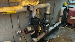
On hydronic systems, we double check system pressure with our calibrated test gauge—we routinely find clogged boiler pressure gauges that have been misleading the previous contractor.
We use our test gauge on a circulator so we can determine system flow from the pump curve. We see far too many circulators with either no gauges or two gauges. No gauges means you have no clue and two gauges means you don’t know how big your gauge error is. We routinely map pipe temperatures to reveal ghost flow, sticking check valves, and incorrectly piped connections between primary and secondary systems.
We get a baseline of incoming propane pressure to our boiler or furnace gas valves.
On control systems, we map out the existing control wiring and confirm voltage drop going to other equipment. We commonly run temporary control wires to remove intermittent control operation as a variable so we can confirm system operation.
All of this diagnostic information starts to create a picture of system operation and leads to our last step: creating a rescue plan.
Step 6: Rescue Plan – Creating a Plan That Restores System Operation
After completing the above steps, we have a much better idea of what is right about the system and what is wrong. We typically start our rescue plan by mapping out the ideal rescue scenario. For example, redoing all of the undersized ductwork, or opening up walls to replace line sets or hydronic supply and return pipes.
We then have to adjust that scenario to accommodate the budget expectations from the homeowner and their appetite for disruption inside the home. During this iterative process, thinking outside the box can be very helpful.
The thoroughness of our diagnostic process and the clarity of our understanding of why the system hasn’t been working correctly goes a long way towards reassuring the homeowner that our plan will be successful.
Their goal is to end the bleeding after spending months or years of struggle with the first contractor as they applied band-aid after band-aid in an effort to get the system to work.
At this stage, we clearly state (CLEARLY STATE) the limitations of our investigation, our rescue plan to achieve the desired system performance, and any possible consequences of decisions to not upgrade the infrastructure as necessary. We can then proceed with the rescue, document our work, and ultimately commission the correctly operating HVAC system. Another successful rescue.
About the Author
Brian Nelson
Brian Nelson is the co-owner of Nelson Mechanical Design, a “green” mechanical contractor serving the energy efficiency and home comfort needs of Martha's Vineyard, MA since 2004. The company designs, installs, and services just about anything to do with heating, cooling, domestic hot water, water treatment, geothermal, heat pumps, and radiant. NMD is committed to preserving the fabric of the Island it calls home. To learn more visit nmdgreen.com.
