Cooling System Rescue – Replacement of the Dinosaur
We see lots of strange things on the Vineyard, but this was the strangest! Back in 2001, this homeowner wanted a HVAC system but had significant constraints on the design. No ductwork between floors—so that meant there would be fan coil units in the upper floors. No drilling—so that meant no geothermal. The remote chiller plant had to be 300 feet from house —so that meant chilled water (as VRV hadn’t arrived in the US yet). No chilled water piping above the basement level—so that meant refrigerant lines to the DX coils in the fan coil units.
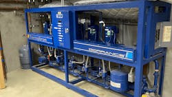
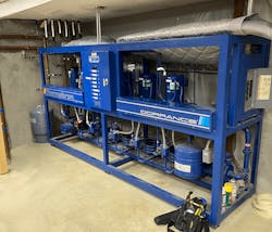
To make all of this happen back in 2001, the HVAC contractor had to cobble together a system built around a Thermaltron R22 compressor rack (which we called the Dinosaur) that was cooled by a remote chilled water plant and sent refrigerant to the six fan coil units throughout the house.
This system, while profoundly inefficient, was effective enough that it lasted more than twenty years. When service bills (failed compressors, failed circulators, clogged heat exchangers) started to pile up, the homeowner turned to us for a complete retrofit of this system.
The homeowner again stated his conditions—he wanted to leave the six aging fan coil units in place, re-use the line sets buried in the walls, and connect to the existing remote chilled water plant. And make the system more efficient. And make it quieter. And make it easier to service. And make the installation beautiful.
The good thing was that the Thermaltron Dinosaur was very inefficient, loud, and difficult to service so replacing that would get us halfway there. But what would we replace it with that would work with chilled water and DX coils? Our first thought was a geothermal split system, but they were no longer made using R22. So we would need to source new R410a DX coils for the fan coil units and confirm that the line sets buried in the walls would work based on their size and total length.
Existing System Issues – Temperature Cascade, Inadequate Flow in Loop, Refrigerant Leaks
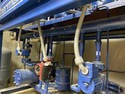
The Thermaltron Dinosaur was really inefficient and really looked like a nicely painted science experiment. We noticed that all the compressors were different brands and models, all of the water to refrigerant heat exchangers were different brands and models, and there was a horrible temperature cascade across the entire rack with the first compressor getting nice cool water and the sixth compressor struggling with water heated up by the previous 5 compressors! (No wonder compressors 5 and 6 had been changed numerous times over the past 20 years.)
Our first goal was to break up the DX load into six individual heat pumps going from water to refrigerant. We also knew that there were refrigerant leaks—but were they in the Thermaltron or the DX coils or the line sets? The homeowner was also concerned about the condition of the blower motors in the six fan coil units, so he asked us to replace those as well. We knew from our entering and leaving water temperatures going to and from the remote chiller plant that we had inadequate water flow through the Thermaltron. We could only guess the size and length of the buried water lines and the homeowner did not want to disturb the landscaping. So easiest path forward was to split up the pumping duties and create separate inside and outside water loops.
Refrigerant Investigation and First Design Steps
We had quite a list of things to do. We would start with the demo of the Thermaltron, remove the R22 DX coils in the six fan coil units, and then individually test all 12 liquid and vapor copper lines that served these DX coils.
Next, we would do our pressure drop calculations to correctly size the pump that would connect the remote outside chiller plant with a new buffer tank (which we needed to smooth out the thermal load and make connection between inside and outside loop pumps easy).
We would then select water to DX heat pumps that could tolerate our existing line set lengths and copper tube diameters and easily work with new R410 TXVs and coils. The pressure drop across the heat pump heat exchangers would inform our selection of an inside loop pump between the buffer tank and the new heat pumps.
Lastly, we needed to locate new R410s DX coils for the six fan coil units. The knowledgeable folks at Sustainable Coils were able to match the dimensions of the existing R22 coils and make new R410a DX coils with attached TXVs.
Demo Begins and Project Moves Forward
We broke up the Thermaltron into small enough pieces to remove from the basement. It took a while to recover all of the refrigerant and cut free all of the 12 liquid and vapor lines.
Once it was out of the way, we brazed up pressure test ports for our nitrogen test. We removed the six DX coils from the six fan coils and tested all of the copper lines to 400 psi. We were very grateful when we discovered that they all held pressure! No leaks in the buried line sets! The homeowner was relieved that we wouldn’t need to open up any walls inside his home to replace any lines.
We made careful measurements of the DX coils and Sustainable Coils was able to create new coils that would drop in without any modifications and work with R410a and with the replacement blower motors. After evaluating several water to DX heat pumps, we went with Climatemaster as their Tranquility heat pump could work with our existing line sets sizes and lengths.
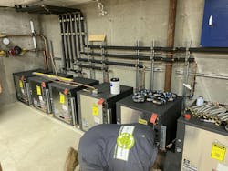
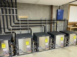
Now that we had settled on a heat pump model, we started layout of our new system in the basement. We had a firm constraint of length from the basement corner to the stairs. We had to set them in a row of six heat pumps as the homeowner did not want us to stack them on a rack. Noise was a critical concern, so he wanted the ability to add additional sound treatments if necessary as the living room was directly above this mechanical space.
Inside and Outside Water Loop
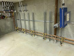
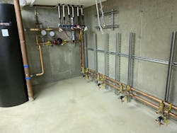
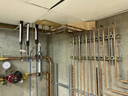
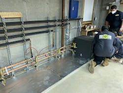
We installed a framework of strut on the wall and laid out the footprint of the six heat pumps. We then installed water lines to supply the six heat pumps with inside loop water.
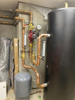
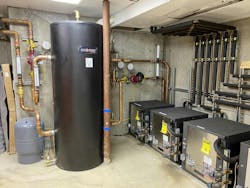
Spacing was critical as there was only an inch to spare across the six heat pumps. We installed a 120-gallon buffer tank to smooth out the operation of the remote chiller plant and the inside heat pumps.
Our pump selection for the inside circulator was easy as we knew the pressure drop across the new heat pumps and our new piping. The homeowner opted for simplicity and wanted a single speed circulator instead of variable speed pressure dependent pumping. We did insist on pump operation only when there was a call for cooling.
(There is way too much uncontrolled constant pumping in mechanical systems across the globe. Sure, it is easy and makes controls simple, but it is a lazy approach that wastes an enormous amount of energy. Just say no!)
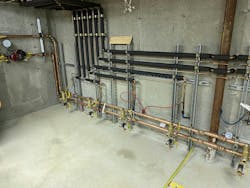
The pump selection for the outside piping was a little more involved as we had to guess the pressure drop across the remote chiller plant and the buried piping between the plant and the basement. We installed the tees for the supply and return for each heat pump in precisely the right location so that we could slide the heat pumps in place and make our water connections in the front. Each heat pump got its own air separator and purge points.
Refrigerant Piping – Homeowner Insists on Hard Copper
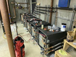
We had determined that there were no leaks in the vapor or liquid lines going to the six DX coils in the fan coil units. We got the replacement drop-in coils from Sustainable Coils, complete with new TXVs, and brazed those in at the fan coil units. We then redid the pressure test and then started our refrigerant piping layout. The homeowner wanted the look of hard copper pipe for the refrigerant lines so we used a lot of smaller Hydrazorb cushion clamps.
Just like the water lines, we had to carefully lay out the refrigerant piping for each heat pump so it would land in the space between heat pumps. We then pressure tested our braze joints again and insulated the vapor lines.
Installation and Connection of New Heat Pumps
The homeowner had asked for a low-profile installation of the six heat pumps and piping so they would have more options if sound mitigation steps were necessary. This had dictated our layout of six heat pumps in a row.
Because they wanted noise and vibration isolation from the floor as well, we simply laid out 2” foil faced foam and slid the heat pumps into place.
We were grateful that they all fit! We were able to complete the water and refrigerant piping between the units and make the connections at the front of each heat pump. Then we completed final pressure testing of all refrigerant connections and proceeded with evacuation and refrigerant charging at each heat pump. We found no leaks on the water side (thank you press fittings) to each heat pump and the individual air separators did the air purging for us.
Commissioning and Operation
Controls for this system were simple: each of the six thermostats turned on their respective fan coil unit blower and sent a call for cooling to their respective heat pump in the basement mechanical room. Each heat pump then energized a relay; the six relays were wired in parallel to the outside and inside loop pumps so that they would only run if there was a cooling call. The remote chiller plant outside was looking at loop temperature so when it saw that the buffer tank temp was rising, it would turn on.
Each zone cooled nicely, and the new heat pumps were much quieter than the old Thermaltron Dinosaur! The homeowner was happy and decided that they didn’t need any additional noise reduction measures. Another successful cooling rescue.
About the Author
Brian Nelson
Brian Nelson is the co-owner of Nelson Mechanical Design, a “green” mechanical contractor serving the energy efficiency and home comfort needs of Martha's Vineyard, MA since 2004. The company designs, installs, and services just about anything to do with heating, cooling, domestic hot water, water treatment, geothermal, heat pumps, and radiant. NMD is committed to preserving the fabric of the Island it calls home. To learn more visit nmdgreen.com.
