Chilled Water Rescue – No More Dead Compressors
We got a call from a homeowner after his HVAC service company threw up their hands and said they could do no more to get the cooling system to work. They had recently replaced two failed compressors and had just discovered that a third compressor was dead. We conducted a site visit to get a handle on the HVAC installation and what the possible causes of compressor failure might be. The homeowner was tired of paying for repairs and was ready to make the necessary changes to get a reliable and effective cooling system.
During our investigation it became clear what was killing these compressors—they were 150 feet away from the house. The existing system had three 5-ton residential duty condensers, located in the adjacent woods, connected to three brazed flat plate heat exchangers in the basement of the house via 150 feet of copper line sets. The water side of each of the flat plate heat exchangers was connected to a constant circulation chilled water loop which served cooling coils in six air handlers. Each air handler had a three-way zone valve to bypass chilled water through the cooling coil when there was a call for cooling.
It was amazing that the compressors lasted as long as they did in this scenario; eventually a lack of oil return and excessive starts and stops destroyed all of them one by one. After replacing the second compressor, the homeowner finally agreed that this installation would never offer reliable and efficient cooling. It took the failure of the third compressor to convince him that major changes in this system were necessary.
We were asked to develop a plan for a chilled water rescue that would remove the pumping noise from the basement (and living room directly above) by relocating the constant circulation pump, increase cooling capacity, add redundancy, and simplify maintenance and repairs.
We suggested that instead of making the chilled water inside in the basement mech room (which meant connecting the remote condensing units with the house via the 150 foot refrigerant line sets), we would make chilled water at the remote condensing unit location and connect to the house with 150 foot chilled water pipes. This would mean a shift to a glycol system for freeze protection but we would solve the compressor oil return and longevity issues.
Space Limitations
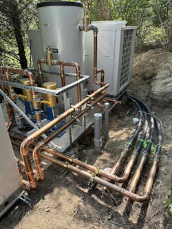
The existing concrete chiller pad had three 5-ton condensing units on it and was screened from the house with trees and shrubs. We proposed the expansion of the pad to accommodate four 5-ton chillers, two circulators, and a buffer tank.
We would dig up the 150-foot copper line sets that ran between the pad and basement and replace them with two 2” poly supply pipes and two 2” poly return pipes.
We quickly realized that we would have to fight for every inch of concrete pad as the homeowner would not permit relocating of any of the trees and shrubs around the existing pad. We had to mockup all of the equipment, piping, fittings, and access space for future maintenance to arrive at the absolute minimum pad size that would work.
The contractor poured the concrete extension of the existing pad, the landscaper dug a 150-foot long trench to expose and remove the lines sets, and we installed our poly pipes between the pad and the basement mechanical space.
We chose to run two supplies and two returns so that our pressure drop between the pad and house would be reduced.
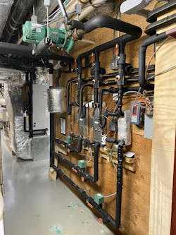
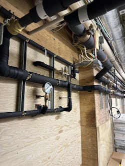
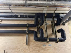
Once inside the basement, we joined the two supplies and two returns and transitioned to 2” copper.
No More Pumping Inside the Building
The existing chilled water system was a constant circulation dinosaur. The circulation pump mounted to the ceiling of the basement mech room sent chilled water to each of the six air handlers regardless of load or demand. At each air handler, the three-way zone valve connected to the chilled water coil would bypass chilled water unless there was a cooling call. When this system was installed no one was worried about energy use so there were no control wires from the air handlers to the basement mech room to control this circulation pump.
Our design was to install pressure sensing circulation pumps so that over time the chilled water three-way zone valves could be replaced with two-way zone valves at each fan coil and we could reduce unnecessary chilled water pumping. Relocating the circulation pumps to the outside chiller pad would also remove the constant vibration in the living room that aggravated the homeowner all summer long.
We connected our pressure gauge to both inlet and outlet of the existing chilled water pump and from the pump curve determined the existing flow and pressure drop. This would be a critical part of our pump sizing calculation. We then demoed the existing flat plate heat exchangers and circulator pump and connected our new supply and return pipes to the existing chilled water system.
Layout of Equipment on the Chiller Pad
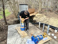
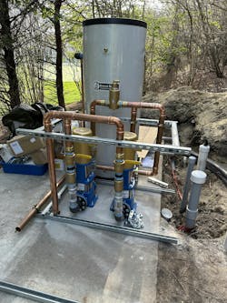
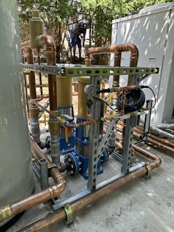
Now that we had completed the inside work, we could pivot to the chiller pad work. We carefully shifted around the two circulating pumps, buffer tank, and four cardboard squares representing the four chillers as we looked for the optimal arrangement. We quickly realized that we would have to forego traditional pump appurtenances due to the extreme space constraints. We would have to go vertical after the inlet and outlet of each pump to give us room for flexes, check valves, and isolation valves. This required a lot of mocking up of the fittings and pipe to determine how things would land once the four chillers were in place.
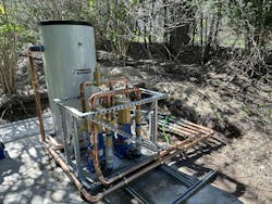
We also had to think forward to how we would sneak the four chillers through the existing trees and shrubs without damaging them. There was no room for a crane or excavator to help us with equipment movement, so we had get creative. We ended up attaching a grid of strut to the concrete pad; we could move the chillers on rollers over to the strut and then slide the chillers in place. We mocked up the supply and return piping for the four chillers to see how we could connect all of them to the 120-gallon buffer tank within our space constraints. It looked like it would work out on paper with little room for error.
Pumps and Buffer Tank Piping is Complete
Once our mockup was complete we were ready to commit ourselves and press everything up. We had to install extra strut everywhere to make sure our press tool didn’t betray us as we pressed everything together. We pressed in large air separators on the return sides of the pumps and the buffer tank and added tees for pressure gauges, pressure sensors, and thermometers. Our buffer tank had four ports—the four chillers (with internal pumps) would connect their supplies and returns to two of the ports and the other ports would connect to the house via the two pumps. We connected the pumps to the two poly supplies and two poly returns that ran 150 feet back to the basement mechanical room.
Moving in the Four Chillers – Don’t Hurt the Trees!
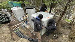
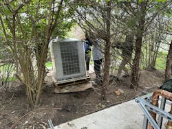
We laid down plywood across the grass so that we could roll the chillers from the street to the edge of the woods next to our chiller pad. We had to be careful not to damage any of the trees or shrubs.
We carefully walked each of the chillers through the narrow opening between the trees onto the concrete pad. At that point, we slid each chiller onto rollers and easily rolled them into place on our strut. Sliding the units on the strut was easy. We then bolted each chiller into place on the strut grid.
Connecting Chillers to the Buffer Tank
This was arguably the hardest part of the job—designing the piping for each of the chillers to connect their supplies and returns together so that it was elegant, easy to service, and easy to install. We did have a few fittings that had to be pressed first before everything else, but we managed not to press ourselves into a corner.
Each of the two chillers were connected together and then the two pairs were connected at the buffer tank. We tried to balance run and branch flow between all four chillers with our piping and fittings. The piping was completed and we filled the system with water (no leaks! Press made it easy!) and then a glycol water mix.
Start Up and Operation
We brought over the pump start-up guru from America (living on the island of Martha’s Vineyard can be very isolating—no McDonald’s or Dunkins—but the guru refused to bring us any Big Macs!) and he commissioned the two variable speed drives that powered the two pumps.
We started up the four chillers and easily hit our target of 44 F. The homeowner appreciated the sound of no-pumping in the basement below his living room. The contractor constructed a shed structure to protect our pumps from the elements. Another successful chilled water rescue with no more failed compressors!
Parts & Equipment
Goulds pumps and drives
Viega press fittings
Spirovent air separators
Hydrazorb strut clamps
Superstrut strut fittings
Weiss thermometers and gauges
Multiaqua chillers
Mueller compression fittings
Flexhose flexible connectors
HTP Boiler Buddy buffer tank
Armaflex insulation and fittings
About the Author
Brian Nelson
Brian Nelson is the co-owner of Nelson Mechanical Design, a “green” mechanical contractor serving the energy efficiency and home comfort needs of Martha's Vineyard, MA since 2004. The company designs, installs, and services just about anything to do with heating, cooling, domestic hot water, water treatment, geothermal, heat pumps, and radiant. NMD is committed to preserving the fabric of the Island it calls home. To learn more visit nmdgreen.com.
