Modern Hydronic Distribution - Circa 1962!
We walked into the room and there it was, just like in the picture, installed in 1962. I can be sure of that because I noticed the cornerstone of the church as we went to the office to meet an old friend of the industry I hadn’t seen in years. Turns out, he was too busy doing paperwork to come to church. I completely understood, because he works for the city and they like their employees to spend a lot of time doing paperwork.
He volunteers at the church on the building committee since he knows HVAC, growing up in the business as the third generation. I was with his brother, who took on that family business. He was going to quote the job. The idea was for me to give them some ideas on modernizing the equipment, since I have been advising this heating company for almost forty years, starting with their father, the second generation running the company. He has long ago retired and moved to Florida, as so many do here in the Midwest, but we still play golf every year when he’s in town for the summer.
The System
The church is heating with the boilers and pumps installed in 1962, when they installed two separate boilers and heating systems for two buildings, locating both boilers in one of the buildings. The boiler room had two large cast iron atmospheric draft hot water boilers sitting side by side, their flues connected to one large chimney.
That was the only thing they shared. Each had its own piping distribution system. The one on the right had three zone pumps, on the return as I remember, which was very common in 1962. Nothing unusual there. The idea of the boiler on the supply side pumping away from the expansion tank connection wasn’t well known back then. Or so I thought.
The boiler on the left had one large pump on the supply side piping, with the expansion tank connected to a tapping on the boiler, so it was pumping away from the expansion tank connection. Whoever piped this was utilizing modern (for 1962) piping technology.
Reading Hieroglyphics
I was told that there was a room with more pumps in it, in the other building. The piping leaving the boiler on the left went to that room and back. I was intrigued. One of the reasons I still work is my curiosity for finding something different. I was not disappointed with what I found.
It took a while to sort out the piping, even with all those arrows pointing out the direction of flow. Then it took a while to understand what I was looking at. I felt like the guy trying to understand Egyptian hieroglyphics for the first time. What does it all mean and why was it piped this way?
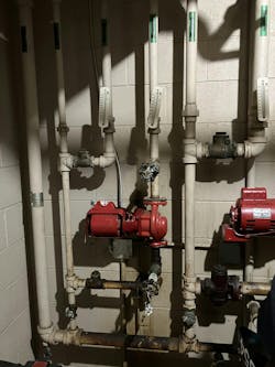
In the photo, you see two of the three pumps that were installed. There were connections on the supply and return for a fourth pump, but they were capped off. They were all piped the same way. On the far left, that is the supply pipe from the remote boiler room flowing down and elbowing to the right. The first tee on the low pipe is pointing up, its branch connection feeding to a plug style balancing valve.
Each of the other tees off the supply pipe have a balancing valve, which would divert, when adjusted properly, just the right amount of water to each of the zones. The first zone might need 20 gallons per minute of flow, while the next zone might need 30 gallons of minute, and so forth. The total flow of that pump back in the boiler room is split three ways and controlled with three balancing valves. Somebody was thinking on this job.
After the balancing valve, there is another tee, with the branch connected to a check valve on the first zone and a weighted check valve on the second visible zone. Both are there to prevent flow from circulating backwards through the zone when that zone pump is off, but another zone pump is on. The pumps are circulating water through their zone, in this case up towards the ceiling, past the very 1960s thermometer in the piping.
The return line comes down, past a thermometer, elbows to go through another check valve, to connect to a tee in the vertical supply line. That return tee and the supply tee 18” below it, it finally dawned on me, were a primary-secondary connection, not commonly used in the early 1960s. The second visible pump is piped the same way, as is the third pump in the room, not in the picture.
If it's Working, Why Change It?
Today, we are used to seeing primary-secondary connections on modern near boiler piping, and as one set of closely spaced tees, not three separate sets of closely spaced tees. In this configuration, the pump back in the boiler room is the system pump with the cast iron boiler piped as full flow. The three zone pumps are piped individually as primary-secondary in the remote location. This idea for multiple zone pumps worked for sixty years. Why change that?
What I did propose to modernize the system would have to reuse certain components and minimize piping changes to keep within the church’s budget. The big ticket would be a pair of commercial mod-cons to save operating costs in the future. But instead of keeping the boilers on separate systems, I proposed to combine all the zone pumps to new common distribution piping in the boiler room, with the boiler pair connected to the new common piping with a new primary-secondary connection.
So there would be the three zone pumps from the right boiler and the old boiler pump form the left boiler, still piped to the other three zone pumps, as the other connections to the new common piping. The advantage of this design is boiler redundancy. If one of the boilers doesn’t fire, the other boiler can provide heat into the building, avoiding that dreaded no-heat situation.
Patrick Linhardt is a forty-year veteran of the wholesale side of the hydronic industry who has been designing and troubleshooting steam and hot water heating systems, pumps and controls on an almost daily basis. An educator and author, he is currently Hydronic Manager at the Corken Steel Products Co.
About the Author
Patrick Linhardt
Patrick Linhardt is a forty-one-year veteran of the wholesale side of the hydronic industry who has been designing and troubleshooting steam and hot water heating systems, pumps and controls on an almost daily basis. An educator and author, he is currently Hydronic Manager at the Corken Steel Products Co.

