There's an old proverb that my father used to say - “If you don't learn something new every day, you were either not paying attention, or were gone fishing. And if you were ‘gone fishing,’ and you ‘didn't learn something new,’ you obviously weren't paying attention.”
Looking back, there are things I'd do differently if I could, but none of us can go back in time, so it's best to live and learn, and teach others to avoid your mistakes. Quite some time ago, I presented the designs on a system that incorporated numerous inputs, outputs and buffer tanks along with my then interpretation of primary/secondary piping. It was somewhat of an industry standard at that point in time, looked really pretty, appeared to be relatively functional, but boy was it a pain to purge. It was also a pain to keep air free and had a whole lot more pumps than it really needed. As we grow older, if we pay close attention, we will learn of better, faster and more efficient ways of being able to perform the hydronic miracles.
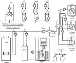
Take a look at figure 1. As you can see, it is essentially a loop. Let's call it the primary loop, with numerous secondary loops for input and output. In reality, we had packaged five pounds of sugar in a two pound bag. It was accessible and orderly, but it had to be installed in such a manner that water flowing through the primary and the secondary loops became cooler and cooler. This required larger heat exchangers, parallel to each other hydraulically speaking and essentially in series with each other thermally, near the end of the loop.
In most conventional systems, this would have spelled disaster for non-condensing heat sources, but in my case, I was using a ground source heat pump, backed up by modulating condensing boilers, so it was not a major concern. If it had been designed with a conventional system, it would have required some means of protecting the gas fired appliances from long term condensation production, probably through control logic, shunting loads to keep the return water temperatures above the condensation point.
Such was not the case, however, due to the continuous declining fluid temperatures. The heat exchangers at the end of the circuit needed to be sized larger to compensate and accommodate lower fluid temperatures seen during maximum load conditions. This required a lot of forethought in initial basic design and layout to avoid a spaghetti mess of piping.
In reality, a person only needs two or three sets of secondary branches to accomplish this feat. One for input, one for outputs and one for buffer tank operation, and that one can be your primary loop. For each design available, there are a hundred ways of doing it, and everyone has their own comfort zone as to how it should be accomplished. This is simply my take on that bent - that's the wonderful world of hydronics.
In order to purge figure 1, you would close the ball valves between the closely spaced tees, and essentially put all loads into series with each other. This saves time when purging. If you choose to do your piping in this manner, remove the handles off of the “tweener” ball valves, and hide them in the jacket of the boiler. No one ever looks in there. Once the system is completely purged, provided that no additional air is introduced (i.e. pump replacement), it remains relatively air free.
Figure 2 represents my thoughts about how I would accomplish this same feat today, given consumers awareness of the cost of electricity and the dire need to be as green as possible. Notice the lower count of secondary connections, for input as well as output, and the incorporation of the buffer tank into the primary loop. Also note that the thermal loads are coming off the primary in a downward manner to avoid the possibility of natural thermal siphon occurring to the upper distribution systems. All take offs from the primary come off the bottom to avoid entrained air that is inevitable during initial start up and any future start ups after significant water removal for service. Why invite air to participate in your games if you can exclude it for the most part?
Instead of having one pump for each heat exchanger inlet, I have incorporated the use of a variable speed circulator and low wattage consumption zone valves at the point of use. This will significantly reduce the wattage of consumption for those heat exchangers. All in all, the new and improved design reduced the number of circulators from 13 to 11. Not earth shaking, but every little bit helps. Also be aware of the dual use of the buffer tank as an air separator. Again, every little bit helps save material and labor costs associated with the installation. As I mentioned earlier in this column, “If you didn't learn something new today, you weren't paying attention.”
Tune in next month as we look at the perceived and real value of annually servicing these wonderful modulating/condensing appliances. Until then, happy high efficiency hydronicing.
Mark Eatherton is an independent hydronic/alternative energy heating systems consultant. He is a nationally recognized industry educator/speaker on hydronics and alternative energies. He can be reached at [email protected].
Read more Mark Eatherton articles
About the Author
Mark Eatherton
Mark Eatherton material on this website is protected by Copyright 2017. Any reuse of this material (print or electronic) must first have the expressed written permission of Mark Eatherton and CONTRACTOR Magazine.
